Mine Geometry Models
Stope, cave and development geometry is a fundamental aspect of most geotechnical analysis. Mine geometry also varies over time and capturing these changes is critical in any back analysis or numerical modelling that investigates stability or monitoring parameters over time. This is a utility app to create models of mine geometry that can be exported to facilitate a wide range of applications such as:
- Live surveys
- Mine geometry can be displayed as surfaces in General Analysis and other 3D Views that automatically update with the current time filters. So when you backdate your seismicity to a year ago, the surveys will only show geometry present at the time.
- Volume calculations
- Mining volume can be calculated over time. This allows seismicity and other parameters to be plotted as a function of mine geometry.
- Distance calculations
- It is often important to know the distance of large events or damage locations to the nearest development or stope at the relevant time. This is like the distance to survey tool except time is also taken into account. So you can compute the closest stope at the time of damage or the closest development at the time of the large event.
- Numerical modelling inputs
- The geometry models can be exported in a number of formats, including Map3D .inp format.
The export options will gradually be expanded to more modelling formats such as FLAC, RS3 and Wave. Another possible application is to create block models of lithology or geotechnical domains based on lithology contact wireframes.
Overview
The Mine Geometry Models application provides a comprehensive workflow for creating time-varying 3D models of mine excavations. The app operates through a three-window workflow:
Workflow Structure
- Survey Loading - Load and prepare survey data from your mine geometry
- Build Steps - Convert individual surveys into geometry blocks with temporal and categorical attributes
- Build Models - Merge steps chronologically to create complete mine geometry models
- View & Export - Visualise models and export to various formats for analysis or numerical modelling
The application transforms static survey data into dynamic 4D models (3D space + time) that automatically update based on date filters. This enables powerful time-based analysis capabilities throughout mXrap.
Training Resources
Build steps
Use the automatic boundary box on closed surveys to construct outer blocks and internal blocks. Also assign attributes for model generation.
Build models
Build models from the previously built steps. The model building process occurs by ordering dates to work out the merging and construction process.
Export models
Observe the models generated from the building stages and change the export features for use in numerical modelling or other programs that use inp, dtm, stl & dxf.
General Analysis
Learn how to use the generated MGM models in General Analysis for interpretation.
Building Steps
Steps are the fundamental building blocks of mine geometry models. Each step represents a discrete volume of excavation at a specific point in time with defined attributes.
Survey Selection
The Survey List displays all available surveys organised by folder structure. Use the Folder Levels to Display control to adjust the folder hierarchy depth. Selecting a parent folder automatically selects all child surveys.
Resolution Settings
Resolution determines the dimensions of the blocks used to construct the geometry model. Available resolutions include:
| Resolution | Use Case | Performance |
|---|---|---|
| 1m | High detail for mXrap analysis | Slower |
| 2m | Balanced detail and performance | Moderate |
| 3m | Good for larger excavations | Faster |
| 5m | Whole-mine models, numerical modelling | Fastest |
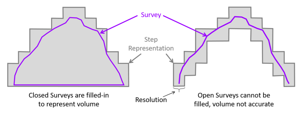
The resolution affects both processing speed and volume accuracy. Smaller resolutions provide more accurate volumes but take longer to process. The model will slightly overestimate volume by an amount proportional to the resolution used.
For mXrap usage, 1-2m resolution is typically appropriate. For numerical modelling packages like Map3D, consider using 3-5m resolution to reduce computational load.
Bounding Box Generation
When you select a survey, the app automatically generates:
- Survey outline - The original survey geometry (purple wireframe)
- Bounding box - Automatic bounds around the survey (adjustable thickness)
- Excavation boundary - The block volume that will be saved as the step
You can override the automatic bounding box if needed to clip specific portions of the survey. However, use this feature carefully - clipping a survey without maintaining a closed surface will result in an incomplete volume.
Block Face Generation
The step building process occurs in two stages:
- Block Faces - Generates the external boundary blocks (typically the longest step)
- Filling - Fills the interior of the boundary blocks using a specialised algorithm (usually fast)
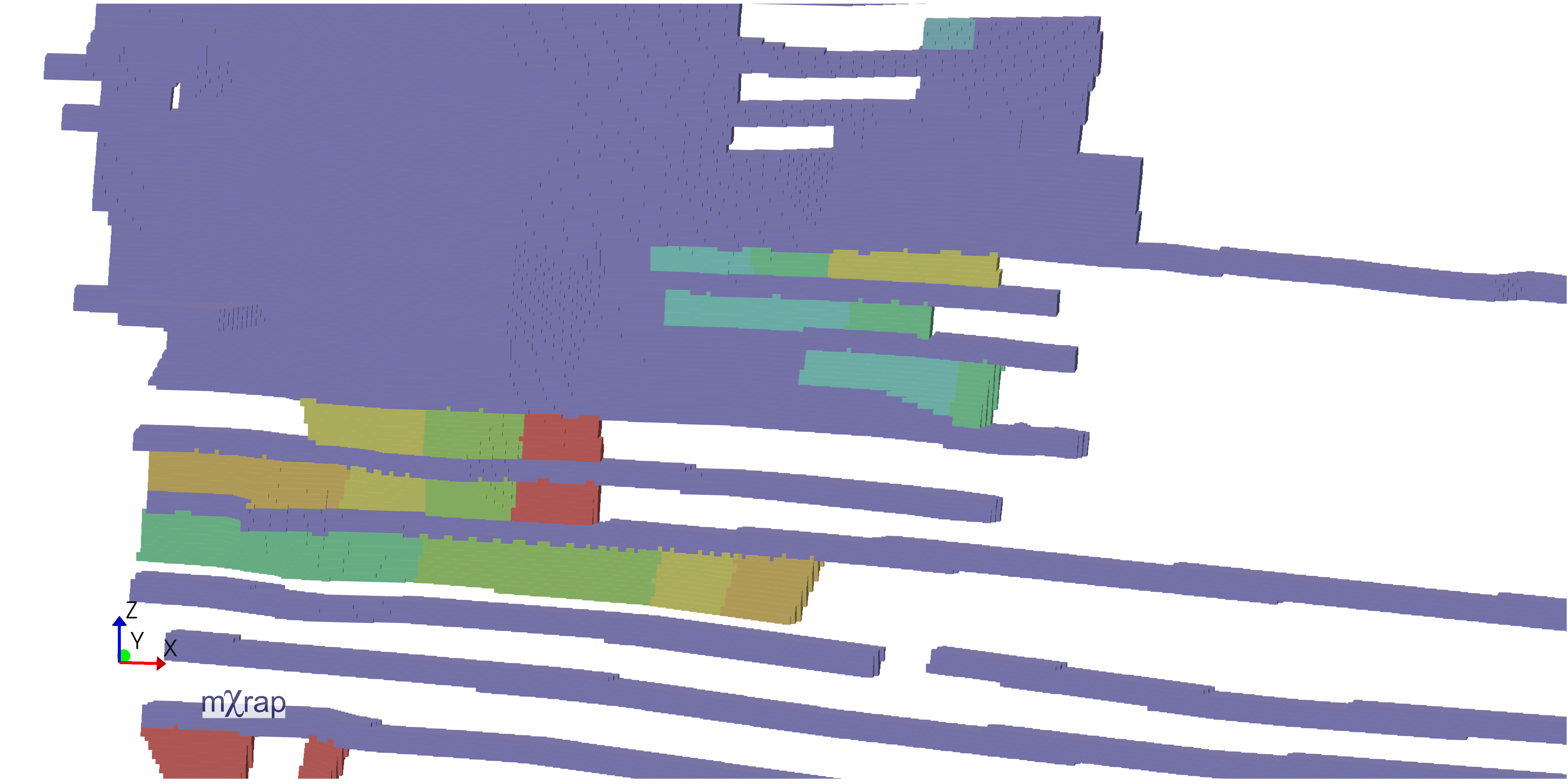
The image above shows how development surveys are converted into block geometry. The app processes the survey to create blocks that represent the excavation volume.
Input surveys must be closed surfaces with no large gaps. If the survey has missing sections (e.g., a cave shape with the bottom completely missing), the app will only create a shell rather than a proper volume, which will not work correctly in model building.
Step Attributes
Each step requires three key attributes:
- Mining Date - The date when this excavation was created or became active
- Type - Classification of the excavation (e.g., Development, Stope, Caving)
- Material - Material classification (e.g., Void, Backfill, Ore)
These attributes are critical for model building as they determine how steps interact when merged chronologically.
Viewing Options
Use the viewing controls to inspect your step before saving:
- Toggle between survey outline, bounding box, and excavation boundary
- Adjust bounding box line thickness for better visibility
- Use wireframe mode to see the relationship between the original survey and the block volume
- Enable clipping planes to inspect internal structure
Building Models
Models are created by merging multiple steps of the same resolution in chronological order. The model building process automatically handles the complex interactions between excavations over time.
Resolution Grouping
You can only build models using steps of the same resolution. The app displays all available resolutions based on your saved steps. Select a resolution to view all steps created at that resolution.
Chronological Processing
The model builder processes steps in ascending date order:
- Processes the earliest step first
- Adds subsequent steps chronologically
- Determines what volumes need to be added or merged
- Continues until all selected steps are processed
The blue line indicates the currently processing step, while green lines show already processed steps.
Intersection Handling
There are two types of intersection calculations:
Same Type and Material
When two steps have the same type and material (e.g., both are Caving/Void):
- The second date's shell is added to the first
- Only the volume relevant to the second date is saved
- This represents expansion of the same excavation type
Different Type or Material
When steps have different types or materials (e.g., Development vs Stope):
- The intersection volume changes from one type to another
- For example, development that becomes a stope
- The overlapping volume is converted rather than added
The date, type, and material attributes significantly affect the final model results. Ensure these are set correctly for each step to achieve accurate time-varying geometry.
Model Naming and Storage
When saving a model:
- Provide a descriptive name (e.g., "All Mine 2m")
- The app shows the save location (Standard Data folder → Mine Geometry)
- Processing time depends on the number of steps and their size
- The app automatically switches to the viewing window when complete
Export Options
The Mine Geometry Models app provides three distinct model formats, each optimised for different use cases.
Model Format Comparison
| Format | Description | Best For | Export Formats |
|---|---|---|---|
| Boundary Surfaces | Step boundaries only (blocked format) | Visual analysis, lightweight exports | INP, DTM, STL, DXF |
| Block Model | Complete volume with all internal blocks | Numerical modelling (Map3D, FLAC) | INP only |
| Smooth Surfaces | Smoothed recreation of original geometry | Visualisation, presentation | INP, DTM, STL, DXF |
Boundary Surfaces
This format includes only the step boundaries in blocked format. It's ideal for:
- Visual representation of excavation progression
- Lightweight file sizes
- Quick exports for review
The geometry shows the evolution of excavations over time while maintaining the block structure.
Block Model
The block model fills in all intermediate volume between step boundaries:
- Contains complete volumetric information
- Required for numerical modelling packages
- Larger file sizes due to internal blocks
- Only exportable to INP format
This format is essential when you need actual volume information for stress analysis or other numerical modelling applications.
Smooth Surfaces
The smooth surfaces format applies additional processing to create a refined representation:
- Recreates the original survey geometry
- Removes blocky artifacts
- Best visual quality
- Suitable for presentations and reports
Supported File Formats
| Format | Description | Typical Use |
|---|---|---|
| INP | Map3D input format | Numerical modelling |
| DTM | Digital Terrain Model / Structure files | GIS applications, visualisation |
| STL | Stereolithography format | 3D printing, CAD software |
| DXF | AutoCAD Drawing Exchange Format | CAD applications, drafting |
Export Controls
Surface Smoothing Parameters
For smooth surfaces, you can adjust:
- Quality Threshold - Trade-off between triangle count and accuracy
- Minimum Interior Angle - Improves triangle quality for modelling
- Number of Iterations - More iterations = better quality but longer processing
For numerical modelling exports:
- Enable "Permute to Avoid Non-Manifold" option
- Enable "Minimum Interior Angle" option
- Increase Quality Threshold to reduce triangle count
- Increase number of iterations for better mesh quality
- Enable "Make Boundary Surfaces Manifold" for compatibility
Export Process
- Select the desired format (Boundary Surfaces, Block Model, or Smooth Surfaces)
- Provide a descriptive export name
- For INP exports, optionally specify a template file to merge control parameters and materials
- Click the export button for your desired file format
- Access exported files via the "Open Mine Geometry Folder" link
Exported files are organised in subfolders by format type (INP, DTM, STL, DXF) within the Mine Geometry folder.
Integration with General Analysis
Once you cache a model as your master model, it becomes available throughout mXrap with powerful time-aware capabilities.
Live Surveys
The geometry model appears as a new series in General Analysis called "Geometry Model." This series:
- Automatically updates based on current date filters
- Only displays geometry present within the selected time range
- Hides future excavations when backdating analysis
- Enables time-slice analysis through your mine's development history
Marker Styles and Filtering
customise the display of your geometry model:
- By Type - colour code by excavation type (Development, Stope, Caving)
- By Material - Distinguish between Void, Backfill, Ore, etc.
- By Date - Visualise excavation sequence (blue to red = oldest to newest)
- Highlight Recent - Emphasize recent excavations (e.g., last 3 months in black)
Transparency and Visibility Controls
Control what geometry is displayed:
- Adjust transparency levels for better visibility of internal features
- Toggle individual materials on/off
- Toggle individual types on/off
- Filter by specific steps using the step list
Distance Calculations
The Events table includes two new time-aware distance columns:
- Distance to Closest Geometry - Distance to any geometry in the model (development, stopes, etc.)
- Distance to Closest Development - Distance specifically to development excavations
These calculations are time-aware: for an event in 2018, the distance is calculated to the closest geometry that existed at that time, excluding future excavations. This differs from standard distance-to-survey calculations which don't account for temporal relationships.
Time-Slice Analysis
Use the time-slice feature to step through your mine's history:
- Set the date filter to a specific time period
- Geometry automatically updates to show only excavations present at that time
- Seismic events and other data update simultaneously
- Analyse spatial relationships as they existed historically
This capability is invaluable for back-analysis of seismic events, damage incidents, or other time-dependent phenomena.
Best Practices
Survey Preparation
- Ensure all input surveys are closed surfaces with no large gaps
- Verify survey quality before creating steps
- Use consistent naming conventions for easy identification
- Organise surveys in logical folder structures
Resolution Selection
- Start with 2m resolution for general mXrap usage
- Use 1m resolution only when high detail is critical
- Increase to 3-5m for whole-mine models or numerical modelling
- Consider processing time vs. accuracy requirements
Step Attributes
- Set accurate mining dates for proper chronological ordering
- Use consistent Type and Material classifications across all steps
- Add descriptive comments to steps for future reference
- Review step attributes before building models
Model Building
- Build separate models for different resolutions
- Select only the steps needed for your specific analysis
- Monitor processing progress for large models
- Verify model results in the viewing window before exporting
Export Optimization
- Use Boundary Surfaces for lightweight visual exports
- Use Block Model when volumetric data is required
- Use Smooth Surfaces for presentations and reports
- Adjust smoothing parameters based on intended use
- Enable manifold options for numerical modelling compatibility
Workflow Efficiency
- Create steps in batches for similar excavations
- Save models with descriptive names indicating resolution and content
- Cache your primary model as the master for mXrap integration
- Regularly update your master model as new surveys become available
Troubleshooting
Step Building Issues
Problem: Step generation fails or produces unexpected results
- Verify the input survey is a closed surface
- Check for large gaps or missing sections in the survey
- Ensure the survey has sufficient detail for the selected resolution
- Try increasing the resolution if the survey is very detailed
Problem: Processing takes too long
- Increase the resolution (larger blocks = faster processing)
- Reduce the survey complexity if possible
- Process smaller sections separately if needed
Model Building Issues
Problem: Model results don't match expectations
- Verify step dates are correct and in proper chronological order
- Check that Type and Material attributes are set correctly
- Review intersection handling for steps with different attributes
- Ensure all steps use the same resolution
Problem: Steps are missing from the model
- Confirm steps are selected (ticked) in the step list
- Verify the resolution matches the model being built
- Check that step dates fall within the expected range
Export Issues
Problem: Export option is greyed out
- The file may be too large for that format
- Try increasing the Quality Threshold to reduce triangle count
- Consider exporting in a different format
- Split the model into smaller sections if necessary
Problem: Exported model doesn't work in numerical modelling software
- Enable "Permute to Avoid Non-Manifold" option
- Enable "Make Boundary Surfaces Manifold" option
- Increase the Minimum Interior Angle setting
- Verify the export format is compatible with your software
General Analysis Integration Issues
Problem: Geometry model doesn't appear in General Analysis
- Ensure you've clicked "Cache Model as Master"
- Reload data in General Analysis
- Verify the model file exists in the Mine Geometry folder
Problem: Distance calculations show unexpected values
- Remember that distances are time-aware
- Verify the event dates and geometry dates are correct
- Check that the geometry existed at the time of the event
Advanced Applications
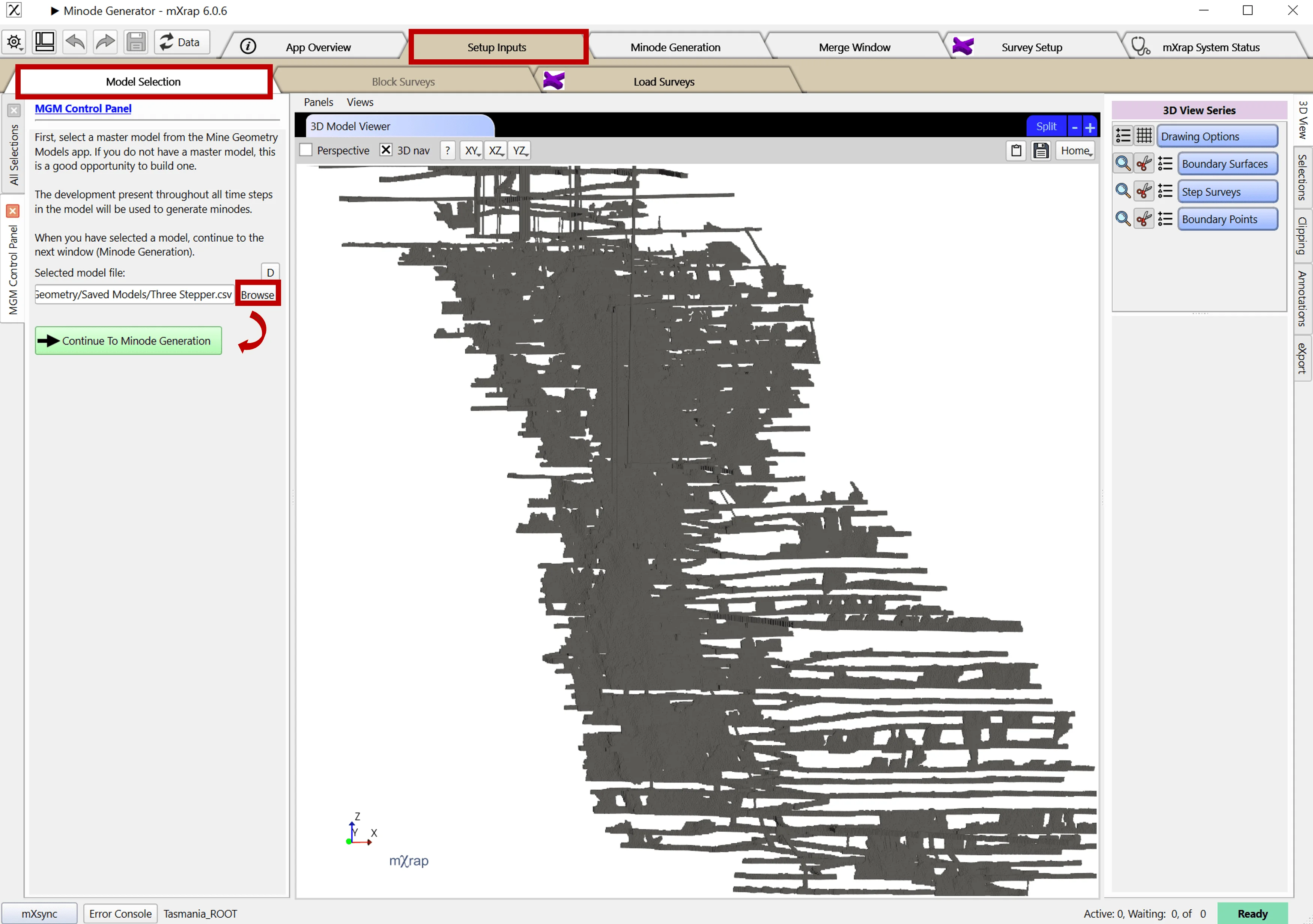
Minode Generation
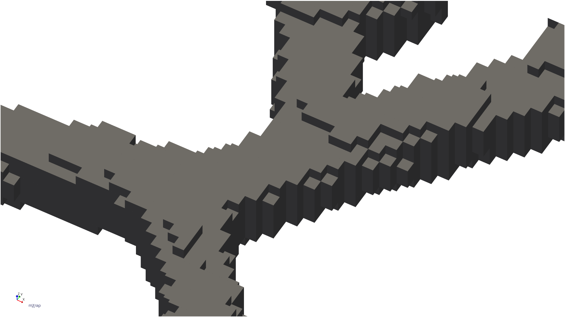
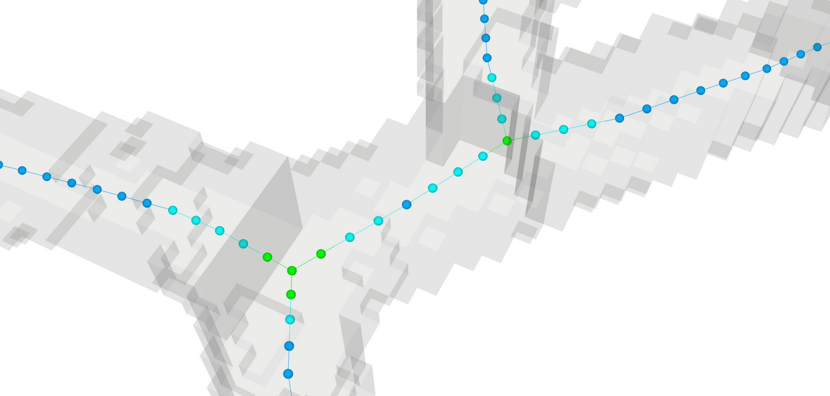
Mine geometry models can be used to automatically generate minodes for hazard assessment applications. The Minode Generator app processes geometry blocks to create centerlines through development excavations.
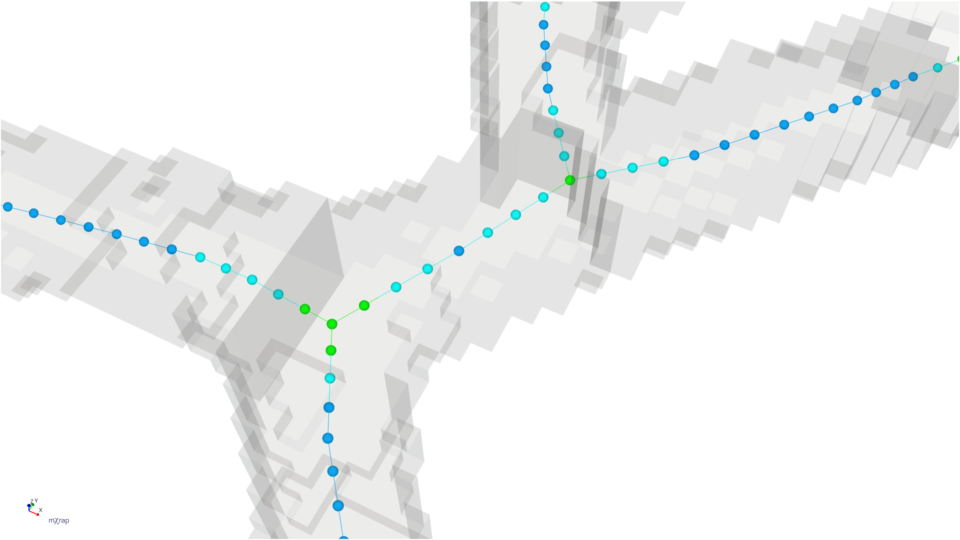
The image shows how development blocks are thinned to create lines through the center of excavations, with calculated effective span and height at each point. These minodes can be time-filtered to show only development present during specific assessment periods.
Related Documentation
- Minode Generator - Generate minodes from mine geometry models for hazard assessment
- Survey Format Converter - Convert and optimise survey formats
- General Analysis - Use geometry models for time-varying analysis
- Hazard Assessment - Apply time-filtered minodes in hazard calculations